بسم الله
Having learned about the structure of operating systems, this article will — God willing — serve as your reference for understanding interrupts.
Our method in this series is to tie examples to the terms and concepts we take on, and you will find illustrative images and code to deepen understanding.
Computer-System Organization
Before diving into our subject, we must understand how a computer system is organized — main concepts do not stand without foundations to build understanding upon; no one sells fish to someone standing on the seashore.
A computer system consists of one or more CPUs and several device controllers connected through a common System Bus. This bus allows communication between components — controllers and CPUs — and access to shared memory:
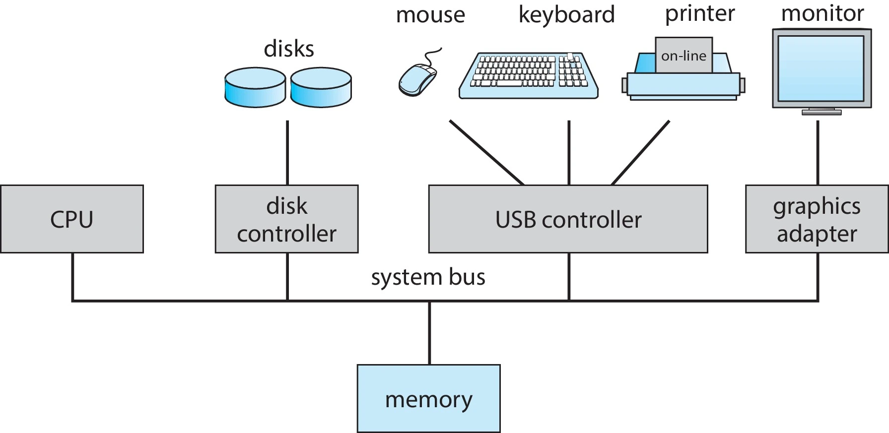 Figure (1): Computer system organization
This system has essential components worth knowing:
1. Device Controllers: Responsible for specific devices (such as disk drivers, audio devices, graphics displays).
A key point about device controllers: one controller may manage several devices (a single USB port, for example, can serve a mouse and a keyboard).
How is data transferred between the device controllers and the CPUs? Each device controller contains a local buffer and special-purpose registers that help it communicate.
2. Device Drivers: A dedicated program per controller; the driver understands its controller and offers the rest of the operating system a uniform interface to the device — meaning it lets the kernel talk to the controller:
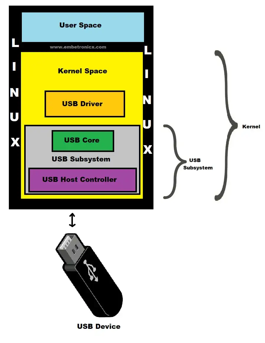 Figure (2): Where device drivers sit
3. Parallel Execution: The CPU and the device controllers run in parallel, all competing for memory cycles:
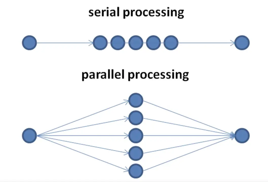 Figure (3): Components competing for memory cycles
4. Memory Controller: Regulates access to shared memory to prevent collisions — memory access is synchronized through it:
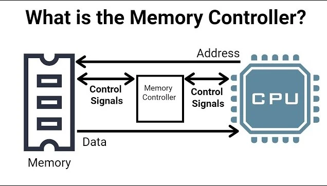 Figure (4): Synchronized memory access
How Does an I/O Operation Unfold?
We will learn how this system works by explaining interrupts. Let us take as an example a computational process where a program performs an I/O operation.
To start the I/O, the device driver loads the appropriate data into the device controller’s registers. The controller then examines the contents of those registers to determine what action to take (such as reading a character from the keyboard). The controller starts transferring data from the device into its local buffer; once the transfer completes, it informs the device driver that the operation finished.
The driver then hands control to other parts of the operating system. It may return the data itself, or a pointer to where the data sits in memory if the operation was a “read”, and it may return status information such as “operation completed successfully” or “device busy”.
The question: how does the device controller notify the device driver that it finished? That happens via an interrupt.
What Is an Interrupt?
Hardware can trigger an interrupt at any moment by sending a signal over the bus to the CPU. (A system may have more than one bus, but the system bus is the primary communication path between the main components.) Interrupts are used for many purposes and are a fundamental part of how operating systems interact with hardware.
An assembly example — a typical keyboard-interrupt handler:
push  eax        ; save the register before using it
in    al, 60h    ; read the key's scan code from keyboard data port 60h
mov   al, 20h    ; load the EOI value (0x20) into AL — this is not a read!
out   20h, al    ; send End Of Interrupt to the PIC's control port (0x20)
pop   eax        ; restore the register
iret             ; return from interrupt
Note the sequence: we read the key’s scan code from port 60h, then send the interrupt controller (PIC) an end-of-service signal (value 0x20 through port 20h) so it knows we finished handling this interrupt and can accept new ones.
So when an interrupt is sent to the CPU, what happens?
The CPU stops what it was doing immediately and transfers execution to a fixed location. And what does this location contain? Usually the starting address where the interrupt service routine (ISR) resides.
We can think of the ISR as an organizing center for interrupts — it manages their affairs. After execution transfers to the fixed location, the ISR runs; when it completes, the processor resumes the work that was interrupted:
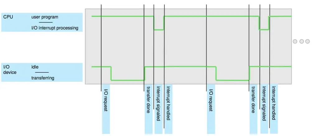 Figure (5): From the interrupt signal to the service routine
Interrupts are thus an important part of computer architecture: every computer design has its own interrupt mechanism, along with many shared functions. The interrupt must transfer control to the proper interrupt service routine.
The Interrupt Vector
How does that happen exactly?
The direct way to manage this transfer is invoking a generic routine that examines the interrupt information and then calls the interrupt-specific handler. But interrupts must be handled quickly since they occur frequently, so instead of that generic routine we can use a pointer table of interrupt routines for the necessary speed: the interrupt routine is invoked indirectly through this table, with no intermediate dispatcher needed.
Generally this pointer table lives in low memory (roughly the first hundred locations), and these locations hold the addresses of the interrupt service routines.
This array — called the interrupt vector — is indexed by a unique number supplied with the interrupt request to provide the address of the ISR belonging to the interrupting device. This is the approach Windows and Unix systems use for delivering interrupts.
Saved State
How are the interrupted computation’s details recovered once the processor returns?
The interrupt infrastructure must save the state information of whatever was interrupted so it can restore that information after processing the interrupt. Sometimes the ISR needs to alter the processor’s state (by modifying register values, for instance) — what must happen then? The routine must explicitly save the current state first, then restore it before returning.
After the interrupt is handled, the saved return address is loaded into the Program Counter, and the interrupted computations resume as though the interrupt never happened.
The Interrupt Mechanism
How does the mechanism work?
The processor has a wire called the interrupt-request line, which the CPU senses after executing every instruction. When the CPU detects that a controller has signaled the line, it reads the interrupt number and jumps to the interrupt-handler routine, using that number as an index into the interrupt vector, and begins execution at the address associated with that index.
What does the interrupt handler do?
It saves whatever state it will change during its operation, determines the cause of the interrupt, performs the required processing, restores the state it saved, executes a return-from-interrupt instruction, and brings the CPU back to the execution state it had before the interrupt:
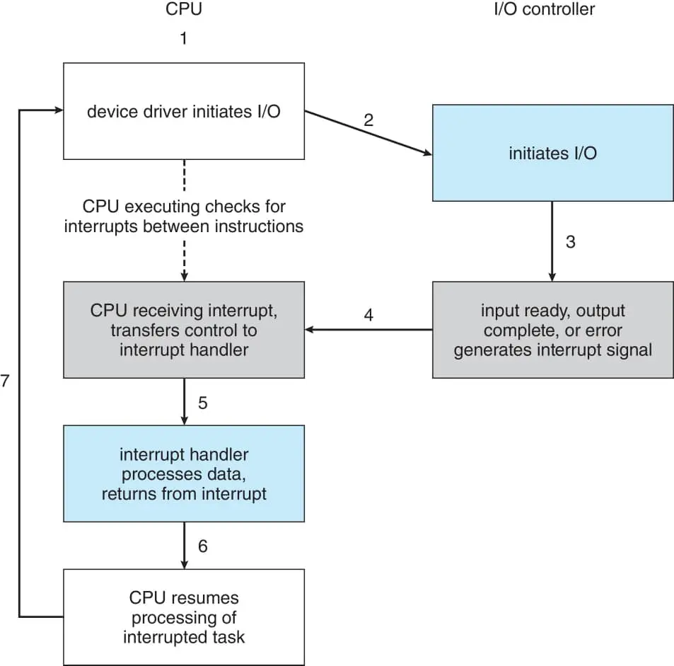 Figure (6): The interrupt mechanism cycle
That whole process is called the interrupt mechanism. Modern systems need more sophisticated features for interrupt handling.
Modern Requirements
What matters most here: the ability to defer interrupt handling during critical processing — imagine the CPU running an essential task and an interrupt arrives mid-task that stops it; the system could crash.
The problem was solved by giving interrupts levels: the OS distinguishes high-priority from low-priority interrupts, responding to each with the appropriate degree of urgency. These features are provided by the CPU together with the interrupt controller.
Modern computers brought a qualitative shift: processors now include two interrupt request lines:
- Nonmaskable: Reserved for events such as unrecoverable memory errors.
- Maskable: These interrupts can be temporarily switched off by the processor — at the OS’s direction — before executing critical instruction sequences that must not be interrupted, then re-enabled afterward.
Interrupt Chaining
But modern systems surfaced a problem:
As we said, the purpose of the interrupt vector mechanism was reducing the need for a single interrupt handler examining every potential source to determine which requires service. In reality, however, computers contain more devices — hence more interrupting handlers — than there are address elements in the interrupt vector.
How was that solved?
Through interrupt chaining: each element of the interrupt vector points to the head of a list of interrupt handlers. When an interrupt occurs, the handlers in the list are called one by one until the correct one is found.
This structure is a compromise between the overhead of a huge interrupt table and the inefficiency of dispatching to a single interrupt handler. This image shows the interrupt handler design in Intel processors:
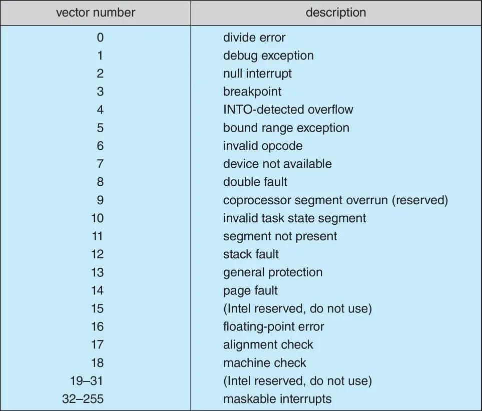 Figure (7): Interrupt vectors on Intel processors
Numbers 0 through 31 signal various error conditions and are nonmaskable.
Numbers 32 through 255 serve purposes like device-generated interrupts and are maskable.
And as noted, an interrupt priority level system lets the processor order interrupts by importance and execute them accordingly.
Summary
All operating systems use interrupts to handle asynchronous events. Interrupts are raised by device controllers and by hardware failures — why? To enable doing the most important work first through the interrupt priority system. Handling interrupts efficiently is essential for good system performance.
Keep us in your prayers.