بسم الله
Peace be upon you. In this series we will cover the x86-64 assembly language and work through hands-on exercises. These articles are distilled from the MACC – FLARE Learning Hub course, which I studied recently; I hope God makes them beneficial for you.
1. Assembly and Disassembly
Let us start by defining some terms that will recur constantly throughout this course:
Assembly Code — often referred to simply as Assembly — is the textual representation of the machine code executed by the processor. It is the highest-level representation of a program that can be reliably recovered without access to the original source code. And while every computer architecture (such as x86, ARM, and MIPS) has its own assembly language, the fundamental principles you will learn here while analyzing x86 and its 64-bit extension (x86-64) are universal.
Disassembly is the process of translating binary machine code back into assembly code. A program called a Disassembler — such as IDA Pro and Ghidra — analyzes the machine code and generates the corresponding assembly instructions. These instructions use abbreviations called Mnemonics (such as
MOV,ADD, andJMP) to make the machine’s operations human-readable.Decompilation is the process of converting assembly code back into a high-level programming language. Unlike disassembly, decompilation will never perfectly reconstruct the original source code; this is due to compiler optimizations and the permanent loss of original information (such as comments, variable names, and data type definitions). Although it is a “best-effort” approximation, decompilers are indispensable in modern reverse engineering because they allow analysts to understand program behavior at a much higher level of abstraction.
Figure 1.1 illustrates assembly, disassembly, and decompilation:
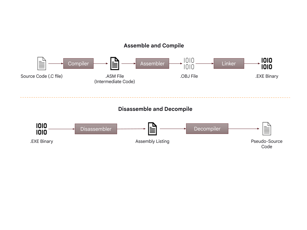
Figure 1.1: The assembly, disassembly, and decompilation pipeline
- The upper half illustrates Compilation: the Compiler translates human-readable source code into an intermediate assembly listing (ASM File). The Assembler then converts that intermediate code into an Object File containing binary machine code. Finally, the Linker resolves all external references and combines several object files and libraries into a single final executable.
- The lower half illustrates Disassembly and Decompilation: as reverse engineers, we receive a compiled executable for analysis. We use a disassembler to produce an assembly listing from the machine code, then leverage a Decompiler to perform a “best-effort” recovery of the high-level source code based on that disassembly.
2. Data Types
Assembly does not have the complex data types you may be used to in high-level programming languages. Instead, assembly primarily deals with the Byte, the Word, the Double Word, and the Quad Word, measuring one, two, four, and eight bytes respectively.
| Windows Type | C Definition | In Assembly (Asm) | Length | Meaning |
|---|---|---|---|---|
BYTE | unsigned char | db | 1 | An unsigned 8-bit value |
WORD | unsigned short | dw | 2 | An unsigned 16-bit value |
DWORD | unsigned long | dd | 4 | An unsigned 32-bit value |
QWORD | unsigned long long | dq | 8 | An unsigned 64-bit value |
Table 1.1: Fundamental data types
In Table 1.1:
- The first column shows the standard names for these data types in the Windows API.
- The second column shows the equivalent type definition in C.
- The third column shows the notation assembly listings typically use to denote a data value:
db— “define byte”dw— “define word”dd— “define double-word”dq— “define quad-word”
3. x86 Registers
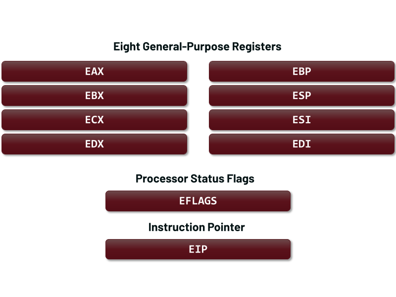
Figure 1.2: The core register set of x86
The x86 architecture has eight general-purpose registers, each 32 bits wide: EAX, EBX, ECX, EDX, ESI, EDI, EBP, and ESP. While most instructions can accept these registers interchangeably as operands, implicit conventions dictate their usage (for example: ESP is dedicated to stack management, and EAX is typically used for function return values).
The EFLAGS register is a 32-bit register holding a variety of status and control flags. These flags reflect the results of arithmetic and logical operations as well as the state of the processor, all of which in turn influence processor behavior.
The EIP register is a 32-bit register storing the memory address of the next instruction to execute. Unlike the general-purpose registers, EIP cannot be modified directly; it is updated implicitly by the processor during instruction fetch, or explicitly by control-flow instructions.
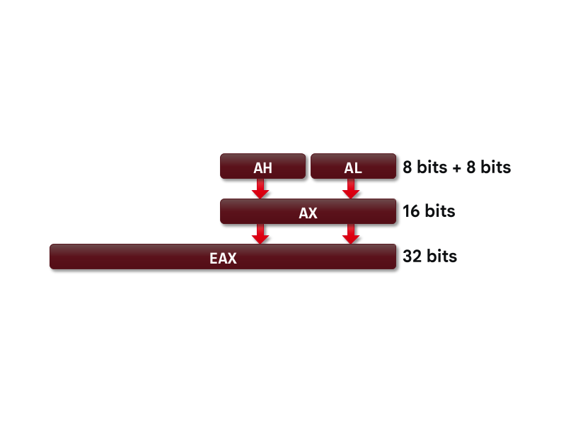
Figure 1.3: Accessing the sub-registers of EAX
The x86 architecture lets instructions access specific portions of the general-purpose registers. Taking EAX as an example, these portions break down as follows:
- Full 32 bits:
EAX - Lower 16 bits:
AX - High/Low 8 bits: the lower 16-bit portion (
AX) splits into two 8-bit registers:AH(the high byte) andAL(the low byte).
| 32-bit | 16-bit | 8-bit (high) | 8-bit (low) |
|---|---|---|---|
EAX | AX | AH | AL |
EBX | BX | BH | BL |
ECX | CX | CH | CL |
EDX | DX | DH | DL |
ESI | SI | — | — |
EDI | DI | — | — |
EBP | BP | — | — |
ESP | SP | — | — |
Table 1.2: General-purpose registers and their sub-registers
All these sub-registers refer to the same physical bits: modifying AL changes the least significant byte of EAX. Additionally, as shown in Table 1.2, while all eight general-purpose registers support 16-bit access, only the first four (EAX, EBX, ECX, EDX) support the H/L 8-bit sub-registers.
4. Instruction Basics
An instruction consists of an Opcode plus any relevant Operands. For every instruction:
- The Opcode is a binary sequence identifying the operation, such as moving data, adding numbers, or calling a subroutine. Together, the opcode and its operands form the machine code (the instruction’s bytes).
- The Mnemonic is a short textual name for the opcode, providing a human-readable representation of the instruction.
- The Operands are the instruction’s arguments; they are either the source data, the destination for the result, or both. Instructions accept a varying number of operands depending on the operation; most require zero, one, or two operands, while some arithmetic instructions require three.
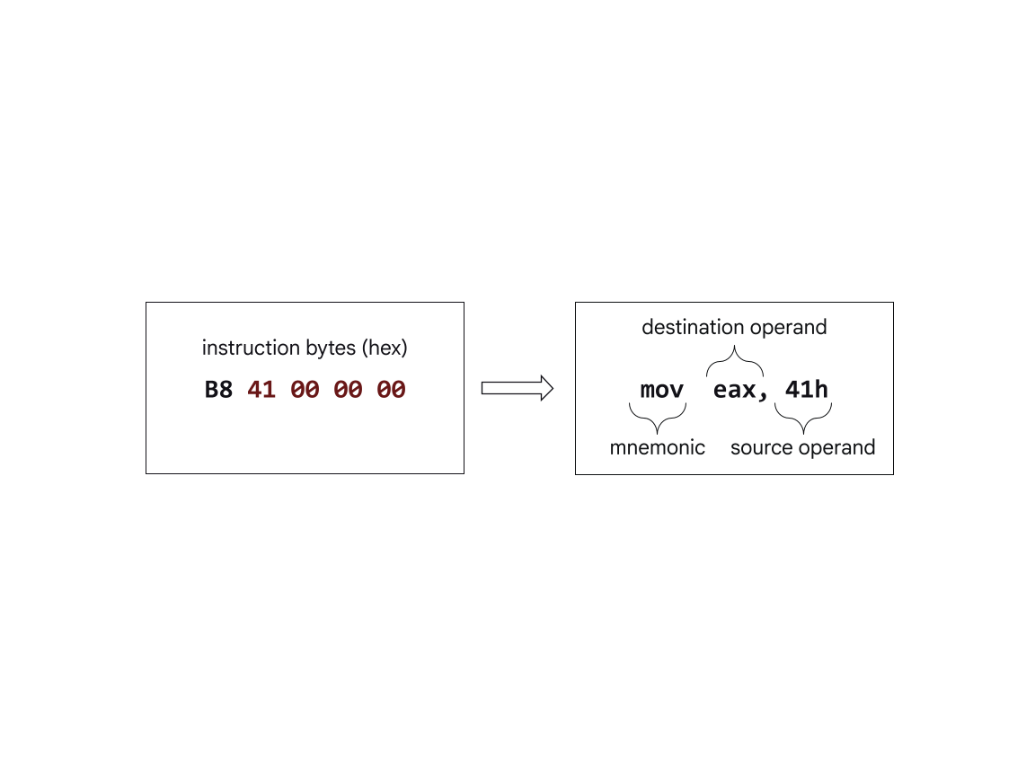
Figure 1.4: A disassembler translates instruction bytes into a mnemonic and operands
In the example in Figure 1.4, the instruction bytes are B8 41 00 00 00, which in assembly translate to the instruction mov eax, 41h:
- The first byte
B8is an opcode meaning “move an immediate value into EAX”. - The remaining four bytes encode the immediate operand value. x86 stores integers little-endian; therefore, for the four-byte value
00000041h, the byte41happears first in memory because it is the least significant byte.
x86 assembly has two main syntaxes: Intel syntax and AT&T syntax. This reference uses Intel syntax, which places the destination operand first and the source operand second.
| Type | Description | Examples |
|---|---|---|
| Immediate | The value is the operand itself | 8, 10h, -123, 120, 'A', 'oleH' |
| Register | The value is stored in a register | eax, si, ecx, esp |
| Memory | The operand refers to the memory location holding the value | [00020001], [ebp+08h], [eax+esi], [esp+ecx+50h] |
Table 1.3: The three classes of instruction operands
Instruction operands fall into three classes: immediates (constants), registers, or memory operands:
- An Immediate operand is a constant encoded directly inside the instruction. Depending on context, this value may be interpreted as a signed number, an unsigned number, or a character.
- A Register operand refers to a register’s contents — usually meaning one of the eight general-purpose registers or their 16-/8-bit sub-registers.
- A Memory operand refers to a specific memory location and is denoted by square brackets
[]. The brackets may contain an arithmetic expression computing the final memory address (referred to as the Effective Address) used in the operation. In most cases, the data at that address is the instruction’s source or destination.
5. The MOV Instruction
Our first x86 instruction is MOV. It moves data from one operand to another. The source can be an immediate, a register, or a memory address, while the destination can be a register or a memory address. But beware: a single MOV cannot move data directly from one memory location to another; to move data between two locations you must first move it through a register.
mov  eax, 0FFh         ; sets EAX = 0xFF
mov  ebx, eax          ; loads the value stored in EAX into EBX
Listing 1.1: Using MOV to load data into registers
In Listing 1.1:
- The first
MOVmoves the immediate value0xFFintoEAX. - The second
MOVloads the value inEAXintoEBX. This operation does not modify the value inEAX.
Most of what programs do is move data from place to place; that is why MOV is among the most common instructions you will see in any x86 program.
Quick Test: MOVin’ on Up
What are the values of
EAXandEBXafter executing the following instruction sequence?
mov ebx, 0
mov eax, 42
mov ebx, eax
Solution (click to reveal)
After execution: EAX = 42 and EBX = 42.
The second instruction loads the value 42 into EAX, then the third copies EAX’s value into EBX, so both registers hold 42 (decimal 42 = 2Ah in hexadecimal).
6. The NOP Instruction
The name NOP stands for “No Operation”. When the processor executes NOP, it does nothing except advance the instruction pointer to the following instruction. Although a “do nothing” instruction might seem useless, it is conveniently used in many scenarios, such as overwriting and removing unwanted instructions in a program. The standard single-byte NOP is encoded as 0x90, which is the opcode of XCHG EAX, EAX: swapping a register with itself is effectively no operation at all.
7. Hacking Assembly with IDA
Note: this section is hands-on and requires an IDA Pro installation on a virtual machine (FLARE-VM recommended).
All Hacking Exercises begin with the program blank.exe. This program contains a large region of NOP instructions ready to be overwritten with the instructions that solve each exercise.
Unless stated otherwise, start every exercise by opening blank.i64 — the IDA database (IDB) file for blank.exe — then press the Continue Process button (the green “Run” button at the top, or the F9 shortcut) to begin debugging the program. If your VM’s path to blank.exe differs from its original location (C:\Users\flare\Desktop\MACC\Exercises\blank.exe), you may see an error saying the input file is missing. If so, adjust the Application and Input file paths under Debugger ➔ Process options to point at blank.exe.
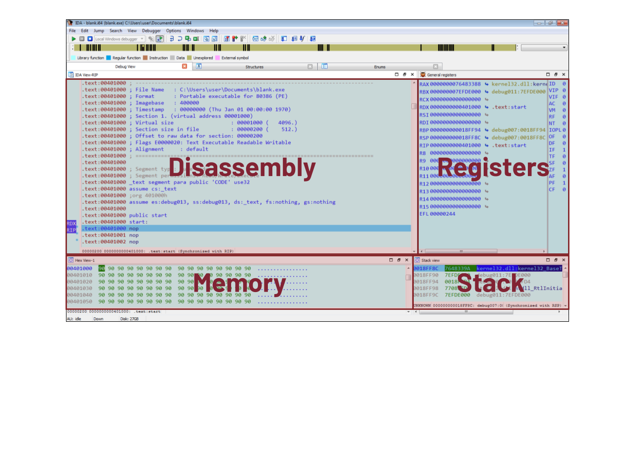
Figure 1.5: IDA’s default debugging layout
Once IDA enters debug mode, the layout changes to resemble Figure 1.5. It divides into four main areas:
- Disassembly: the IDA View window shows the disassembled instructions. In the early exercises, this window will be confined to Text Mode, where instructions are listed linearly by memory address. When your cursor sits inside a defined function, you can switch to Graph Mode, which organizes instructions into Basic Blocks and visually charts control flow between them. This is the window where you will write instructions to solve the exercises; open it via
View ➔ Open subviews ➔ Disassembly. - Registers: the General Registers window shows the current state of the CPU registers. While the debugger is Paused, you can right-click and edit any register’s value. Open via
Debugger ➔ Debugger windows ➔ General registers. - Memory: the Hex View window shows the current memory state. While paused, you can right-click and edit memory. Open via
View ➔ Open subviews ➔ Hex dump. - Stack: the Stack View window shows the current stack state. You can ignore this window in the early exercises until we cover the stack in detail. Open via
Debugger ➔ Debugger windows ➔ Stack view.
To assemble (write) an instruction, select the starting address in the disassembly window then go to Edit ➔ Patch Program ➔ Assemble to bring up the Assembler dialog as in Figure 1.6. Use the X86 Assembly Hacking Zine as a companion reference.
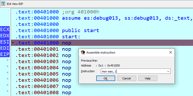
Figure 1.6: Assembling an instruction through IDA’s assembler dialog
To verify or re-patch your assembled instructions, use these debugger operations from the Debugger menu:
- Step over —
F8: executes the next instruction then pauses the debugger. Useful for tracing and analyzing instructions one at a time. - Add breakpoint —
F2: toggles a breakpoint at the instruction under the cursor. Debugging halts execution when a breakpoint is hit. To run a sequence of instructions, set a breakpoint immediately after the last instruction in the sequence and continue (F9). - Set IP: right-click an instruction and choose Set IP to force the instruction pointer onto that instruction’s address. Useful for resetting the instruction pointer to an earlier point in the program.
To start a fresh exercise, terminate the process via Debugger ➔ Terminate process (or the stop button on the debugger toolbar), then do one of the following:
- Close IDA (or
File ➔ Exit). Choose DON’T SAVE for the database when asked, then reopenblank.i64. - Go to
Edit ➔ Patch program ➔ Patched bytes; this window lists all patches made to the database — select every entry and delete them.
Hacking Exercise: movin_up
Assemble and run the instructions of the earlier “MOVin’ on Up” quick test, watching the register values change after each instruction executes.
mov ebx, 0
mov eax, 42
mov ebx, eax
8. Arithmetic Instructions
| Instruction | Description |
|---|---|
add <dest>, <src> | Adds <src> to <dest> and stores the result in <dest>. |
sub <dest>, <src> | Subtracts <src> from <dest> and stores the result in <dest>. |
inc <dest> | Increments <dest> by 1. |
dec <dest> | Decrements <dest> by 1. |
Table 1.4: Core arithmetic instructions
We review four fundamental arithmetic instructions:
ADDcomputes the sum of both operands and stores the result in the destination operand.SUBsubtracts the source from the destination and stores the result in the destination operand.INCandDECadd 1 to and subtract 1 from the destination operand respectively.
For each of these instructions, the destination operand must be a register or a memory location.
9. Bitwise Instructions
| Instruction | Description |
|---|---|
xor <dest>, <src> | Bitwise XOR between <src> and <dest>, result stored in <dest>. |
and <dest>, <src> | Bitwise AND between <src> and <dest>, result stored in <dest>. |
or <dest>, <src> | Bitwise OR between <src> and <dest>, result stored in <dest>. |
shl <dest>, <amount> | Shifts <dest> left by <amount> bits, filling zeros from the right, result in <dest>. |
shr <dest>, <amount> | Shifts <dest> right by <amount> bits, filling zeros from the left, result in <dest>. |
rol <dest>, <amount> | Rotates <dest> left by <amount> bits; bits lost on the left re-enter from the right. |
ror <dest>, <amount> | Rotates <dest> right by <amount> bits; bits lost on the right re-enter from the left. |
Table 1.5: Core bitwise instructions
Bitwise instructions operate on individual bits within the operand:
XOR,AND, andORperform their named logical operations between the two operands and store the result in the destination.SHLandSHRshift the destination’s bits left or right, padding newly entering bits with zeros.ROLandRORrotate the destination’s bits left or right. Unlike shifting, bits that overflow the edge wrap around to the other side, preserving the data.
Hacking Exercise: add_value
Write and execute an instruction sequence that:
- Stores the value
7in registerEAX.- Copies
EAX’s contents intoEBX.- Increments
EAXby 1 usingINC.- Adds
EAXandEBXtogether, storing the result inEAX.
Solution (click to reveal)
mov eax, 7
mov ebx, eax
inc eax
add eax, ebx   ; Result: EAX = 15
10. Accessing Memory
With the exception of LEA (covered later), any operand wrapped in square brackets [] denotes a memory access.
When an instruction accesses memory, the processor must know the size of the data being read or written. Two mechanisms determine this size:
- Inferred Size: if one operand is a register, that register’s size determines the memory access size.
- Explicit Size: if the size cannot be inferred (for example, the source is a constant, or the instruction has only one memory operand), an Operand-Size Directive is required.
In disassemblers like IDA Pro, operand-size directives usually include the data size followed by the word ptr:
dword ptr: a double-word (four-byte) accessword ptr: a word (two-byte) accessbyte ptr: a byte-sized access
; Move 4 bytes of data from address 402000h into eax
mov eax, [402000h]
; Move 2 bytes of data from address 402000h into ax
mov ax, [402000h]
; Move the four-byte constant 0 into address 402000h
mov dword ptr [402000h], 0
; Move the four bytes in ebx to address 402000h
mov [402000h], ebx
Listing 1.2: Memory-access examples using MOV
Listing 1.2 shows a sequence of four MOV instructions touching memory:
- The first reads four bytes from
402000hintoEAX— the destination register’s four-byte size tells the processor how much to read. - The second reads from the same address but only two bytes, since the destination is the 16-bit register
AX. - The third writes the constant
0to402000h. Because0could theoretically fit in a byte, word, or double word, the size is ambiguous — so thedword ptrdirective explicitly tells the processor to write a four-byte zero (00000000h). - The last writes
EBX’s contents to memory; no directive is needed because the size (four bytes) is inferred fromEBX.
Hacking Exercise: beef_inc
IDA tips for this exercise:
- To edit memory in the memory panel:
- Press
F2to begin editing memory.- Press
F2again to commit edits once done.- When typing addresses into the assembler window, append an
hfor hexadecimal (e.g.,401020h).Place the 32-bit value
0xDEADBEEFat memory location401020h. Write and execute an instruction sequence that:
- Loads (MOV) the DWORD at address
401020hintoEAX.- Increments (INC)
EAXby 1.- Stores
EAX’s resulting value back to address401020h.
Solution (click to reveal)
mov eax, [401020h]   ; EAX = 0xDEADBEEF
inc eax              ; EAX = 0xDEADBEF0
mov [402020h], eax
Wait — careful readers will notice the last line above must target the same address:
Corrected solution (click to reveal)
mov eax, [401020h]   ; EAX = 0xDEADBEEF
inc eax              ; EAX = 0xDEADBEF0
mov [401020h], eax
Hacking Exercise: win
Write and execute an instruction sequence that:
- Loads four bytes of data from memory address
401020hintoEAX.- XORs
EAXwith the value0B1FEF9C7h. To enter numbers starting with A–F into the assembler window, prefix them with0.- Writes the modified
EAXback to address401020h.
Solution (click to reveal)
mov eax, [401020h]
xor eax, 0B1FEF9C7h
mov [401020h], eax
11. Memory Operands
Memory operands often involve arithmetic evaluated to yield the final address being accessed. In x86 terminology, this value is called the Effective Address.
The effective address sums up to three components:
- Base: a register holding a starting address.
- Index & Scale: an index register multiplied by a scale factor (1, 2, 4, or 8).
- Displacement: a fixed offset added to the sum; it can be one or four bytes, positive or negative.
The formula generally follows this structure:
Effective Address = Base + Index × Scale + Displacement
; Move 4 bytes of data from ebp+8 into eax
mov eax, [ebp+8]
; Move 4 bytes of data from esp+ebx*4+8 into eax
mov eax, [esp+ebx*4+8]
Listing 1.3: Memory-access examples using MOV with effective-address computation
Listing 1.3 shows two common memory-access patterns:
- The first reads
[ebp+8]; the effective address is baseEBPplus a displacement of 8. - The second computes the effective address as base
ESPplus indexEBXscaled by 4 plus displacement 8 — a pattern seen constantly when iterating array elements.
12. The LEA Instruction (Load Effective Address)
The LEA instruction (lea <dest>, <src>) stands for Load Effective Address. It computes the effective address of the source operand and stores it in the destination.
LEA serves two primary purposes:
- Computing memory offsets, such as finding the address of a local variable or a particular array element. In C/C++, this is the logical equivalent of the “address-of” operator (
&). - Compiler usage to perform simple arithmetic in one instruction instead of chains of arithmetic instructions.
Unlike MOV, LEA does not actually touch memory. When you encounter LEA, pretend the square brackets don’t exist and just “do the math” inside them.
lea eax, [ebx+8]       ; sets eax = ebx + 8
lea eax, [ebx*4+5]     ; sets eax = ebx*4 + 5
lea eax, [ecx+ebx*4+5] ; sets eax = ecx + ebx*4 + 5
Listing 1.4: Computing effective addresses with LEA
In every instruction of Listing 1.4, the destination register receives the value as soon as the math inside the brackets completes.
Hacking Exercise: beef_reader
IDA tips for this exercise:
- To edit memory in the memory panel:
- Press
F2to begin editing memory.- Press
F2again to commit edits once done.- When typing addresses into the assembler window, append an
hfor hexadecimal (e.g.,401020h).Place the 32-bit value
0xDEADBEEFat memory location401020h. Write and execute an instruction sequence that:
- Loads the address
401020hintoEAX.- Loads the 32-bit value stored at the address held in
EAXintoEBX.- Uses LEA to load
ECXwith the memory addressEAX + 2.- Loads the 16-bit value stored at the address held in
ECXintoDX.
Solution (click to reveal)
mov eax, 401020h    ; EAX points to address 401020h
mov ebx, [eax]      ; EBX = 0xDEADBEEF
lea ecx, [eax+2]    ; ECX = 401022h
mov dx, [ecx]       ; DX = 0xBEAD (lower 16 bits)
Lesson Summary
In this chapter we learned the foundations everything else builds upon:
| Concept | Key Points |
|---|---|
| Assembly / Disassembly / Decompilation | Assembly is the highest recoverable representation; disassembly is exact; decompilation is approximate |
| Data types | BYTE (1), WORD (2), DWORD (4), QWORD (8) |
| Registers | 8 general 32-bit registers + EFLAGS + EIP, with sub-registers (AX/AH/AL) |
| Instructions | Opcode + mnemonic + operands (immediate / register / memory) |
MOV | Moves data; never directly between two memory locations |
NOP | No operation; used to overwrite unwanted instructions |
| Arithmetic & bitwise | ADD/SUB/INC/DEC and XOR/AND/OR/SHL/SHR/ROL/ROR |
| Memory | Brackets [] mean a memory access; use dword ptr when ambiguous |
| Effective Address | Base + Index × Scale + Displacement |
LEA | Computes the effective address without touching memory — “just do the math” |
Original source: Malware Analysis Crash Course — FLARE Learning Hub