بسم الله
Having covered the processor and memory topics, this article discusses the third essential part of a computer: the input/output (I/O) system.
The I/O System
As we said before, computer architecture consists of the processor, memory, and external peripherals. Peripherals — like the keyboard and printer — receive data from the outside environment and send data to it, connecting to the processor through special interface units.
These units (I/O Modules) arise to handle the fundamental differences between the processor and peripheral devices, such as:
- Signal type differences: electric/electronic in the processor versus mechanical in the peripherals.
- Transfer rates: devices are naturally slower than the processor.
- Units of information: devices deal in bytes while the processor deals in words.
- Operating modes: devices are asynchronous, unlike the processor’s synchronous operation.
To handle these differences there are interface units linking the processor to the peripherals, which the operating system manages.
How Does the Processor Identify Peripherals to Communicate With Them?
There are two methods of addressing devices:
• Memory-Mapped I/O:
The same address space serves both memory and devices; ordinary processor instructions like mov can access locations representing device registers.
• Port-Mapped I/O:
Each device has its own separate address space, and special instructions like IN/OUT on x86 processors handle communication between the processor and the devices.
Example:
mov  dx, 0x3F8      ; port address (the COM1 serial port)
mov  al, 'A'
out  dx, al         ; send the character 'A' to the device through the port
The Function of I/O Interfaces
What do I/O interfaces do? Two fundamental jobs: synchronizing the speeds of the processor and the peripherals, and providing a shared mechanism for exchanging data.
For example: an I/O interface implements control & timing signals to manage data flow, bridges the speed gap between memory and the peripheral through buffering, and detects transfer errors such as a printer paper jam or noisy bits:
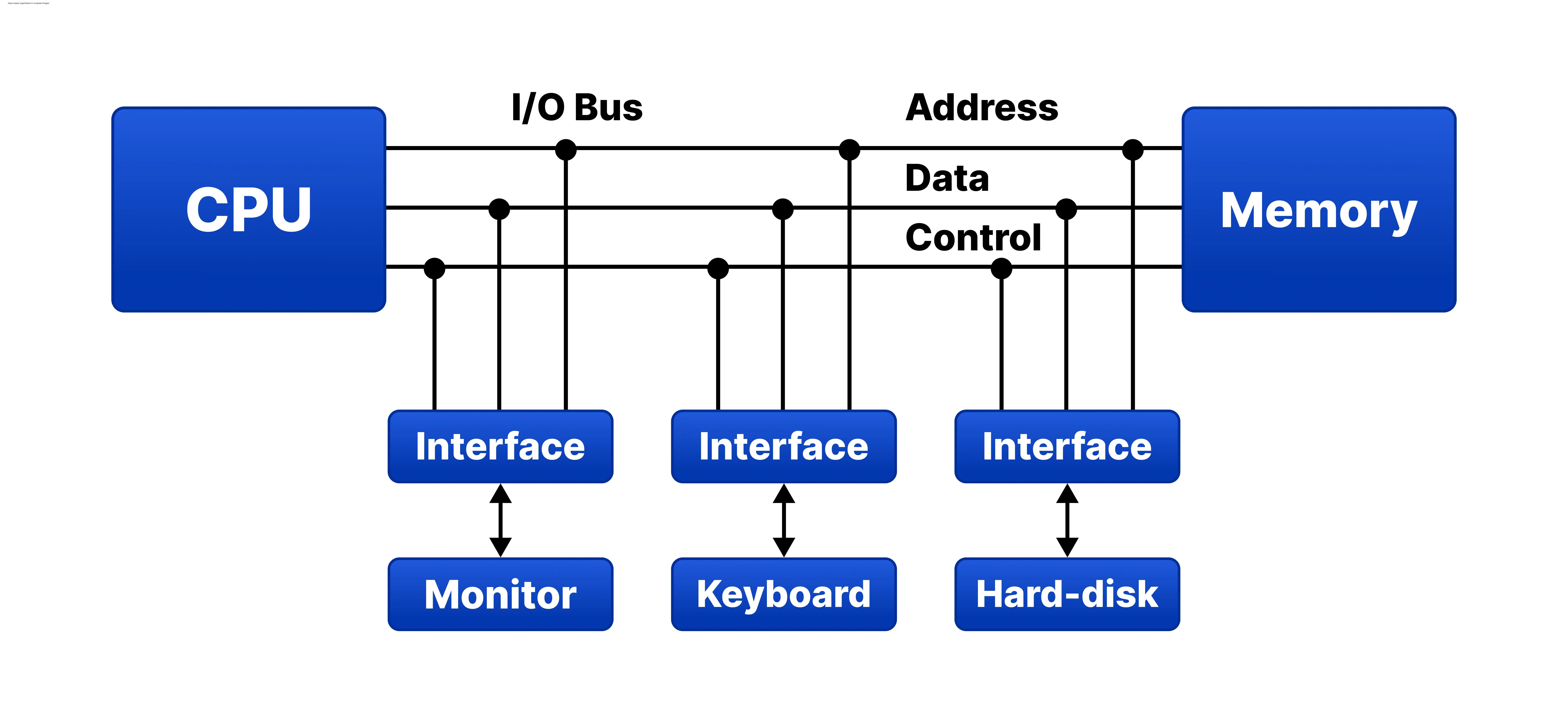 Figure (1): The I/O module and its functions
External Devices
These are everything that connects to the computer for input or output without being a core part of the CPU’s structure.
Every peripheral contains basic components:
• Control Signals: Tell the device what to do (such as sending data to the I/O interface or receiving from it).
• State Signals: Indicate the device’s condition (ready or busy).
• Data Bits: Carry the actual information exchanged between the device and the processor.
For example: we have a keyboard with a ready signal; pressing a key produces a byte sent over the data bus to the processor. This transfer goes through an I/O module that monitors the keyboard’s state and coordinates the transfer.
I/O Modules
What are I/O modules? A dedicated physical component linking peripheral devices to the processor and memory. The module performs two primary functions:
• Interface with the processor/memory: It connects to the processor’s main bus, receiving commands from the processor and returning data to it.
• Interface with peripheral devices: It holds dedicated connections for devices, handling their speed differences and data characteristics.
Detailed Functions
• Control & Timing: Coordinates data flow between memory and devices. For example: the processor sends a read command to the I/O module to check a specific device; the module replies with a status signal describing the device’s state. If the device is ready, the processor requests the data transfer, and the module obtains the byte from the device and delivers it to the processor.
• Processor Communication: Involves receiving commands from the processor (read/write commands) and sending data and status back over the bus.
• Device Communication: Involves processing commands directed at the device and exchanging data and status between the module and the device.
• Data Buffering: Handles the speed mismatch between memory and device: if the device is faster than memory, the module gathers data temporarily before moving it in one batch; if it is slower, it stores data temporarily so the processor and memory are not held up by slow operations.
• Error Detection: Checks for mechanical or electrical errors in the device (like a sheet of paper jamming the printer).
I/O modules connect to the bus via address, data, and control lines. To send a command to a device, the processor places the device’s address on the address lines with the operation type on the control line; the I/O module examines this address and activates the data path to the appropriate device.
I/O Techniques
Modern computers have three principal techniques for synchronizing data transfers between the processor and peripherals:
Programmed I/O
All transfers are driven by instructions in the processor’s program: the program issues a read or write command, then the processor sits in a wait loop, continuously polling the device’s status until it becomes ready. This method is simple in hardware but inefficient performance-wise, since the processor stays occupied checking the device instead of executing other instructions.
Example: polling a device through its port until it is ready:
while (!(inb(STATUS_PORT) & 0x01));  // wait until status becomes READY
data = inb(DATA_PORT);               // read the byte from the port
Interrupt-Driven I/O
This technique solves the problem of wasting processor time waiting: the processor issues the I/O command and continues executing other instructions without waiting, while the I/O module keeps watching the device. When the device becomes ready, the module raises an interrupt signal (IRQ) to alert the processor.
Upon receiving the interrupt, the processor suspends the current program temporarily and hands control to the Interrupt Service Routine (ISR) to read or write the data, then resumes what it was doing before. This technique is far more efficient — a clear performance improvement.
Example:
push  eax
in    al, dx        ; read data from a peripheral's port into AL
pop   eax
iret                ; return from interrupt
Direct Memory Access (DMA)
Used for moving huge blocks of data at high speed (for example to and from hard drives). In this technique the processor sets up the DMA controller — writing the memory address and the count of data to move — then leaves it to transfer the data directly between memory and the device without participating in every single transfer.
The DMA controller acquires the System Bus through arbitration: it asserts a Bus Request signal, the processor answers with Bus Grant, then the controller reads or writes the block at full memory speed. When the transfer completes, it sends an interrupt to inform the processor.
The result of DMA is highly efficient transfers and a processor left free for other tasks — the device reaches memory directly while setup and supervision stay with the processor:
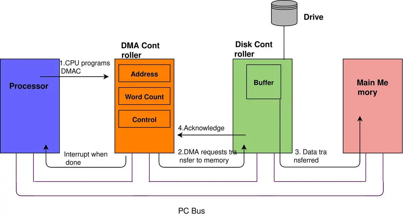 Figure (2): Data transfer through a DMA controller
I hope you remember us in your silent prayers — perhaps one of you stands closer to God, holding a prayer that is never refused.