بسم الله
In the previous article we talked about the ISA and said it defines many things: instructions, data types, registers, memory access, and addressing modes. Since every term there has been covered except addressing modes, this article is dedicated to them, God willing.
A note before we continue: if any shortcoming slips into my explanation of a particular part, that is natural — I do not claim perfection in this series or any other; I only strive toward it. If you spot an incorrect concept or an issue with something, you are welcome to clarify it for everyone’s benefit. And I ask God to make this work sincerely for His sake.
Addressing Modes
In short: these are the ways of telling the processor how to obtain the data or addresses it needs to execute machine or assembly instructions. There are several modes:
• Immediate Addressing: The operand’s value is embedded directly in the instruction itself (the operand field carries a constant used as-is). This means no memory access is needed to fetch the operand.
mov al, 5 ; moves the value 5 directly into AL
• Direct Addressing: The designated field contains the actual memory address of the operand (the instruction explicitly includes a memory address). At execution time, that address is used to reach the memory location holding the operand.
mov ax, [0x0302] ; moves the contents of address 0x0302 into AX
• Indirect Addressing: Here the instruction’s field points to a memory cell or register that holds the operand’s address (so two memory accesses are required: the first to read the actual address, the second to reach the real operand).
mov ax, [bx] ; moves the value stored at the address held in BX into AX
Indirect addressing has an obvious counterpart in C: pointers. For example:
int x = 10;
int *p = &x;
int y = *p;         // p holds x's address; *p then extracts x's value from it
• Register Addressing: The operand — the data of the operation — sits in a processor register (the CPU works directly on registers without touching memory), which makes this mode extremely fast.
mov ax, cx ; moves the contents of CX into AX
• Indexed Addressing: The effective address of the operand is computed by adding an index register’s value to a constant offset.
mov ax, [si + 5] ; effective address = contents of SI + 5
The constant 5 (offset) is added to the contents of SI (index) to produce the final address. This mode is commonly used to access array elements: if SI holds the start address of a byte-sized array, the instruction above reaches the sixth element.
Its C counterpart:
int arr[10];
int x = arr[3];
can be seen as indexed addressing where: address = (base address of arr) + sizeof(int) × 3.
• Base + Offset Addressing: A register holds a base address, and a constant offset embedded in the instruction is added to it.
mov eax, [ebp + 8] ; EBP (base pointer) + offset 8
The contents of EBP are added to 8 to reach the required operand. This mode is useful for accessing function arguments and local variables inside the stack frame relative to the frame pointer, as well as struct fields — the general ptr+offset pattern.
Instruction Format
Instruction format is the bit layout of each command in the binary program, dividing the instruction into distinct fields.
The Fundamental Fields
- Opcode Field: Determines the type of operation the processor will perform — arithmetic, logic, data transfer, a jump, and so on. In short, it is the group of bits encoding the required operation, and its bit width depends on how many operations are supported: with 2ⁿ different operations, the field needs n bits to encode them:
n = 1 => 2¹ = two operations (0 or 1)
n = 2 => 2² = four operations (00, 01, 10, 11)
This is a fundamental principle in designing encoding systems.
- Operand Fields: Refer to the data or addresses participating in the operation; they contain the actual addresses or their locations — pointing at internal registers, memory addresses, or constants, depending on the addressing mode in use.
A uniform instruction structure is essential so the processor knows how to decode every command and execute it correctly.
Example
add R1, R2, R3
- Opcode:
add— indicates addition. - operand1:
R1— destination receiving the result. - operand2:
R2— first operand. - operand3:
R3— second operand.
So the instruction format is a bit-level structure partitioning the instruction into these fields:
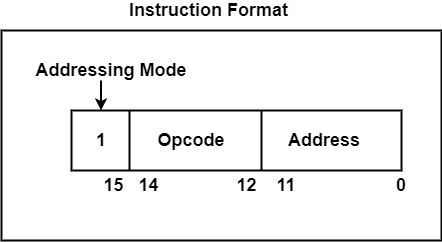 Figure (1): An example of splitting an instruction’s bits into fields
As you can see: the first bit selects the addressing method (direct/indirect), three bits carry the opcode, and twelve bits hold the address.
What Determines the Format Length?
Format length (fixed vs variable): Some architectures use fixed-length instructions whose bit count is known in advance, while others use variable lengths.
For example: all ARM instructions are exactly 4 bytes long, which simplifies decoding and locating each field within the instruction. x86 processors, on the other hand, use variable-length instructions (remember, from 1 to 15 bytes as we saw in the previous article), which makes their instruction encoding more flexible.
I ask God to grant us ample room in knowledge, work, and provision — peace and blessings be upon you.